1.0 Images
2.0 Description
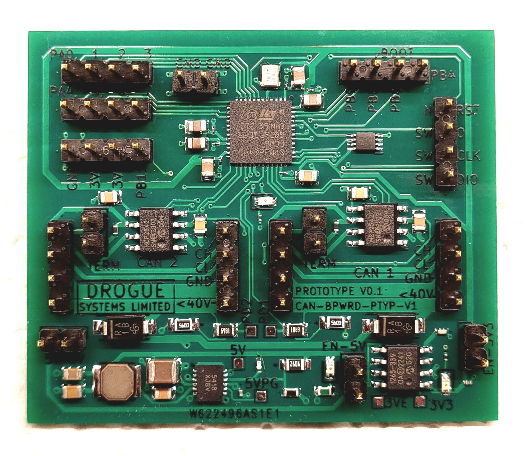
The Drogue Systems CAN-BPWRD is a development board based on the STM32G491 microcontroller unit (MCU). It has 21 I/O pins, enabling the use of UART, SPI, I2C, Timers, PWM, ADC, and of course: CAN.
With a focus on CAN development, the Drogue Systems CAN-BPWRD boasts dual CAN FD transceivers (also compatible with standard CAN) interfaced directly with the FDCAN modules of the STM32 MCU - no SPI translations required!
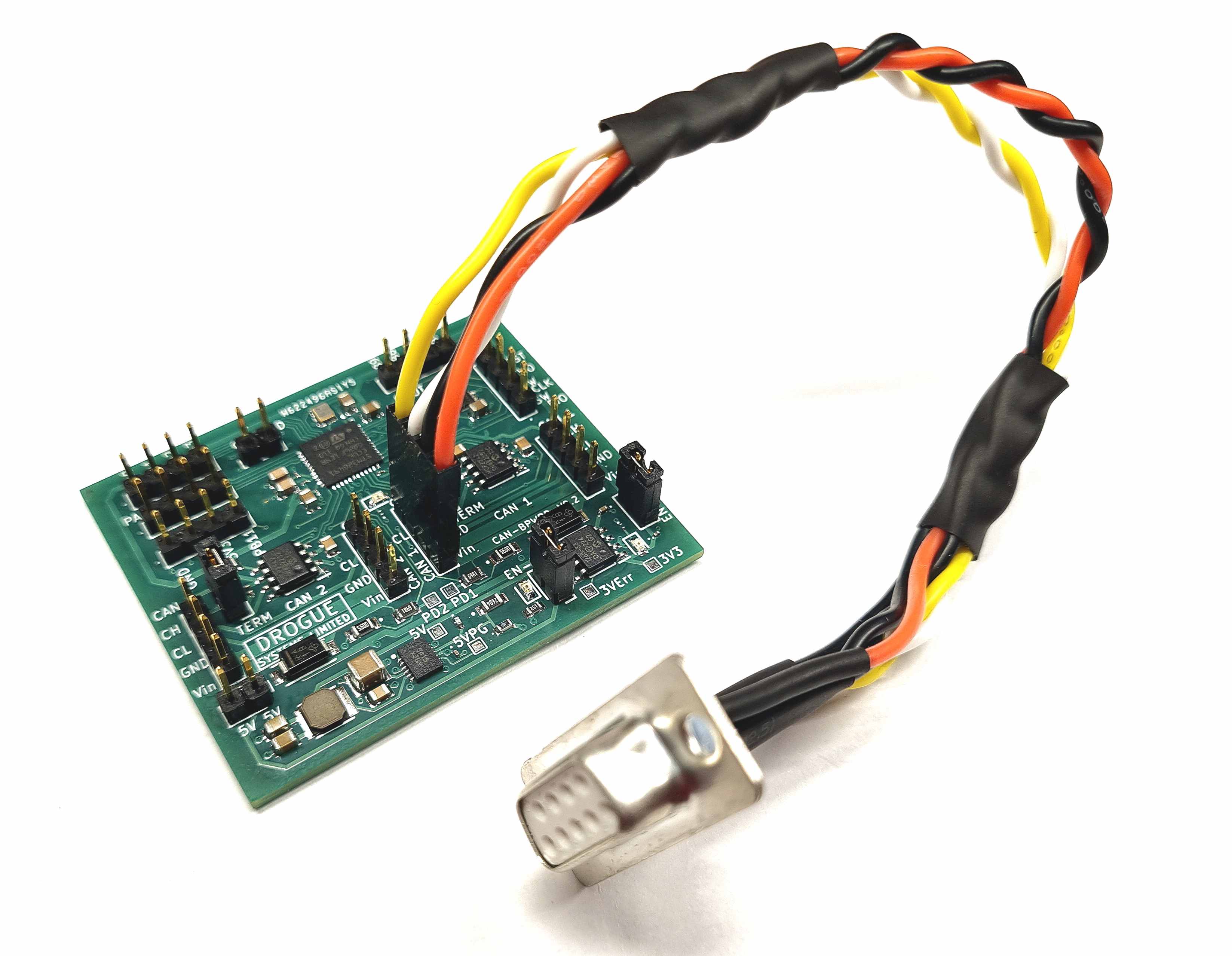
Each CAN interface has an optional 120 ohm termination resistor enabled by a pin jumper, and has two complete sets of pins (Vin, GND, CAN HIGH, CAN LOW) - removing the need for any splitters or large stubs to be added to your network. The Vin pins accept a wide bus voltage range: ~6.5V to 40V, ensuring the board is able to operate even with considerable deviations from the expected 24V nominal.
Designed to be fully compliant with the UCANPHY specification, the two CAN interfaces are completely independent from one another; each Vin acts as a redundant power supply to the development board with reverse current protection. A hard - infinite duration - current limit (1.2A) in the voltage regulator protects the rest of your CAN network from accidental shorts. These features come together to give you the ability to develop and prototype fully redundant, safety critical CAN nodes and software.
32Kb of program accessible persistent storage is available via an EEPROM chip installed on the I2C bus, enabling you to develop firmware which can store and retrieve settings and data at any time - even after power cycles!
The CAN-BPWRD development board is compatible with Cyphal/CAN and can be programmed in multiple frameworks (STM32Cube HAL, Arduino, libopencm3, CMSIS) depending on your preference.
3.0 Basic Specifications
- STM32G491CCU6 MCU (up to 168 MHz)
- 3.3V logic level on I/O pins
- 8 MHz HSE external oscillator
- 2x MCP2542FD CAN FD transceivers (up to 8Mbps, 1Mbps recommended)
- Optional 120 ohm termination on each CAN bus
- Dual redundant power inputs (1 per CAN bus)
- Voltage measuring of each power input using ADC
- N24C32 32 Kbit I2C EEPROM (128 pages x 32 bytes)
- 21 Exposed I/O pins
- 5V, 3V3 and GND pins exposed for general use (~500mA total)
- Program controllable LED
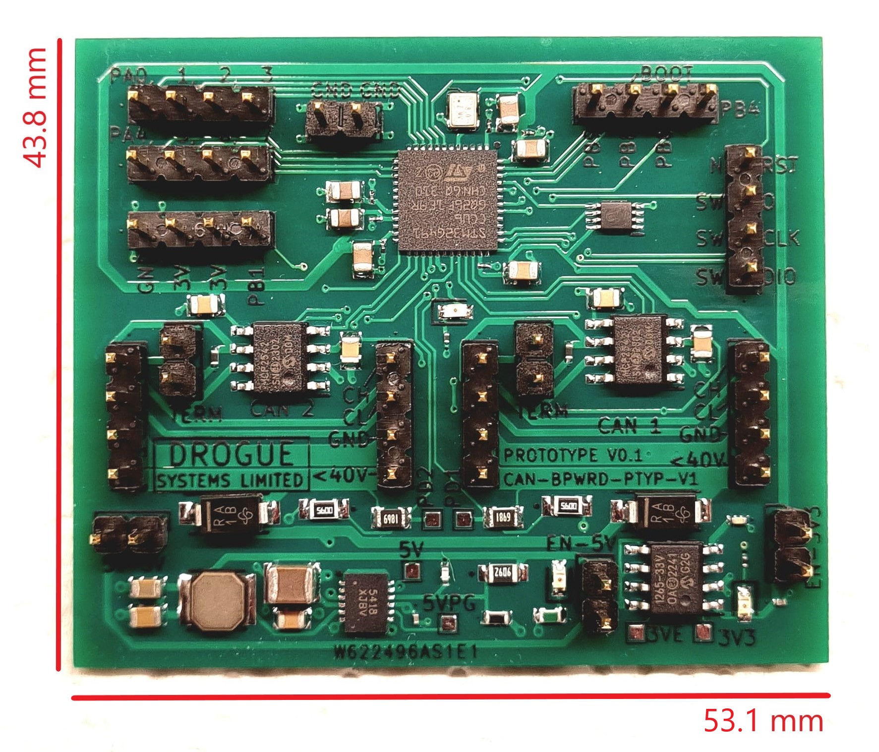
3.1 Physical Specifications
The development board weights approximately 12g.
It measures 53.1mm in width, and 43.8mm in height - when looking at the board top down.