1.0 Pinout Overview
The CAN-BPWRD development board has 2.54mm pitch male pin headers which are compatible with most standard off-the-shelf ‘DuPont’ type jumper/breadboard wires.
The pins on the CAN-BPWRD board can be separated into 3 categories:
- Not Programmable I/O Pins: These are pins such as Vin or GND, which do not provide programmable function.
- Internally Reserved Pins: I/O Pins on the MCU which have dedicated roles on this board, such as the CAN pins or voltage measurement.
- Exposed / Available I/O pins: These pins are available on the pin headers for you to use as you please.
2.0 Not Programmable I/O Pins
2.1 CAN Bus Vin and GND pins
The CAN-BPWRD development board has 4 pairs of CAN bus Vin and GND pins exposed; two pairs for each CAN bus.
The two pairs within a bus are directly connected to one another, providing you the means to pass through the bus voltage to other devices in the network.
By making use of diodes, the two pairs in CAN bus 1 are independent from the two pairs in CAN bus 2. This means you are able to connect two different power supplies - even at different voltages - to the board. The development board will take power from either input, providing redundancy if one was to fail.
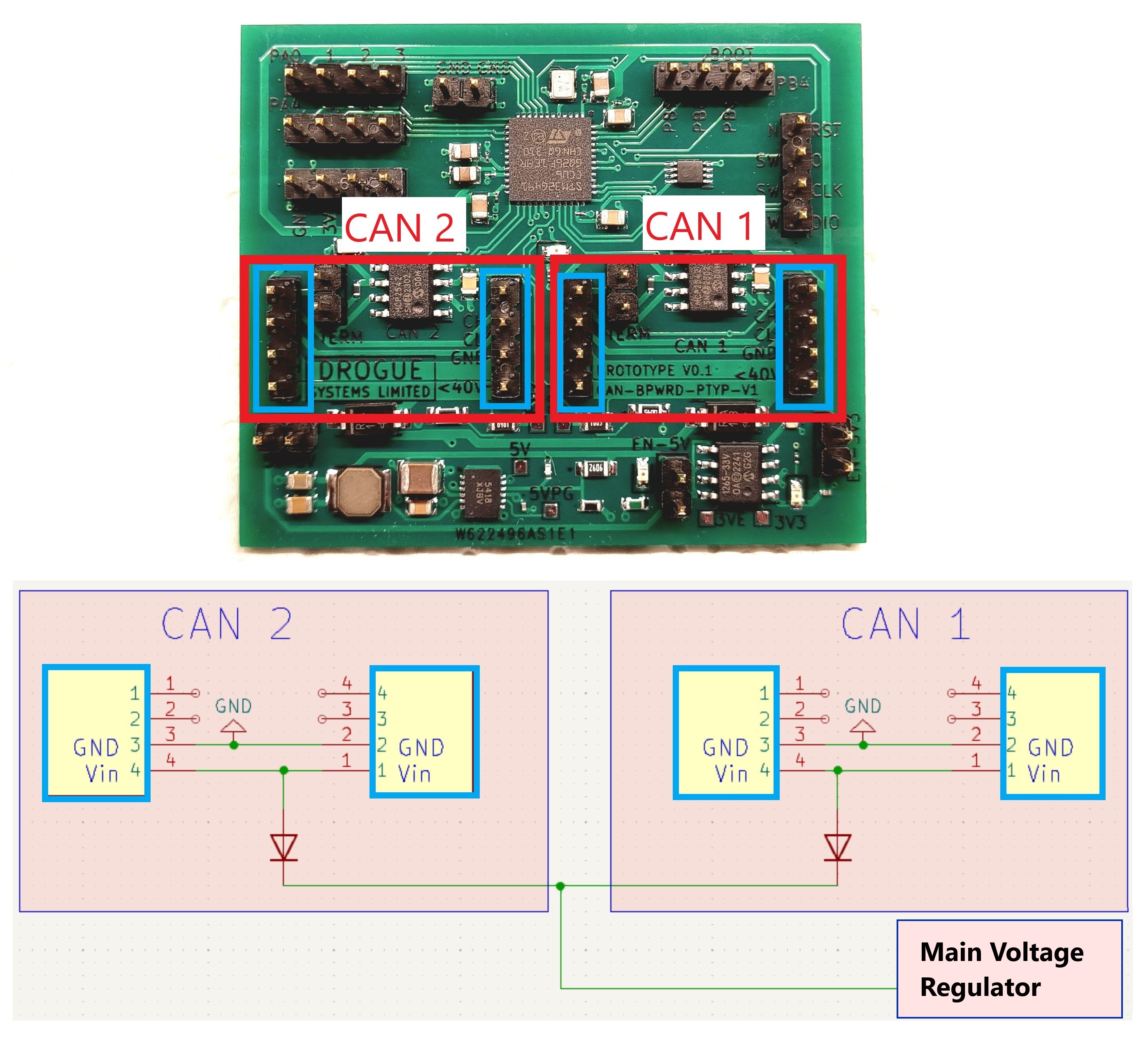
The CAN bus Vin pins are designed to expect a 24V input - as per the UCANPHY specification. However, the acceptable range has been widened to allow ~6.5V* to 40V.
2.2 CAN Termination Jumper Pins
Each CAN bus has pair of pins labeled ‘TERM’, these pins are intended to be optionally shorted together using a jumper to add a termination resistor across the CAN data lines.
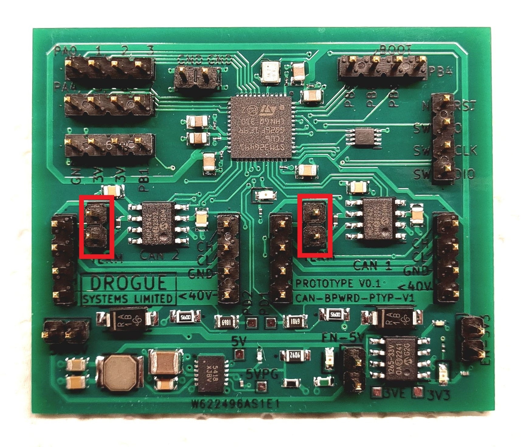
See the CAN-BPWRD CAN documentation page for more information on this function.
2.3 5V and 3V3 Enable Jumper Pins
The CAN-BPWRD development board has pins dedicated to connecting and disconnecting the 5V and 3.3V regulators to the rest of the board.
2.4 General use 5V, 3.3V and GND Pins
3.0 Internally Reserved MCU Pins
Internally …..
| Pin Name | Assigned Function | Description |
|---|---|---|
| PAX | ADCXINX | Read CAN Bus 1 Vin voltage |
| PAX | ADCXINX | Read CAN Bus 2 Vin voltage |
| Item 3 | V0.2 spec | VX.X spec |