1.0 Overview
The CAN-BPWRD Development Board has a number protections and safeties in place in regard to power supply over CAN.
The safeties implemented are often required in the physical specification of many CAN bus standards. For example:
2.0 Dual Power Supply
By making use of diodes, the Vin input CAN bus 1 is independent from the Vin CAN bus 2. This means you are able to connect two different power supplies - even at different voltages - to the board. The development board will take power from either input, providing redundancy if one was to fail.
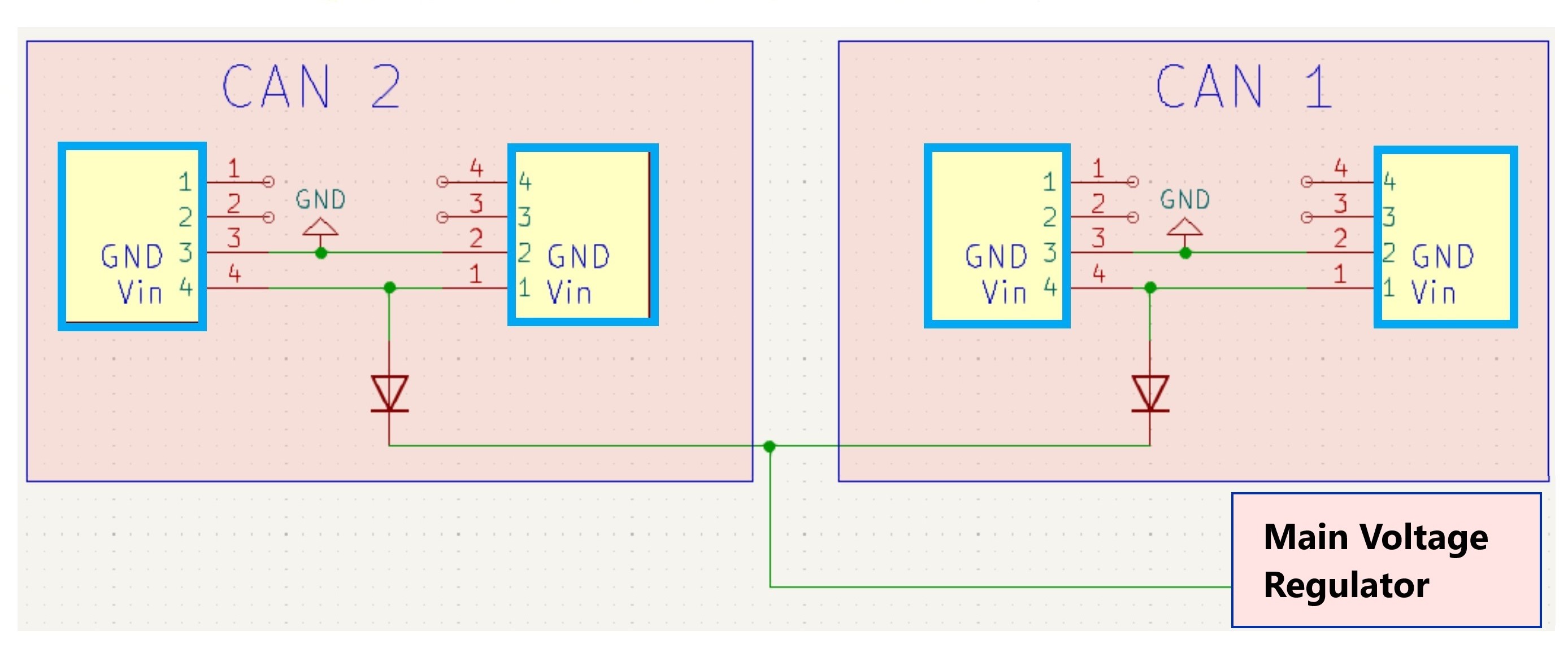
2.1 Reverse Current / Polarity
The diodes on each CAN bus serve to prevent any current flow in the incorrect direction, this mean both primary inputs (CAN 1 Vin and CAN 2 Vin) are protected against incorrect polarity.
2.1 Short Circuit & Over Current
The primary voltage regulator on the development board is the only section of the board directly connected to the CAN bus voltage lines. This regulator generates the 5V supply used by the rest of the board.
The 5V output of the regulator has built in protections which cut the 5V output if a current draw of 1.2A or above is detected. This safety can protect the chip from a short circuit indefinitely.
These protections serve both to protect the development board from some common user errors (shorting 5v outputs to ground) and protects a CAN network from being brought down by the development board if shorted.