An overview of the CAN capabilities of the CAN-BPWRD development board
Important: The CAN-BPWRD Docs are still under development, so may be subject to change.
1.0 Overview
The CAN-BPWRD development board features 2 full CAN interfaces each driven by a MCP2542FD-E/SN CAN transceiver, compatible with both standard CAN and CAN FD.
- For more information, find the data sheet here.
The CAN transceivers are interfaced directly with the CAN peripherals of the STM32 micro-controller (FDCAN1, FDCAN2).
Note: The MCP2542FD supports CAN FD up to 8 Mbps, however a common mode choke is recommended for speed above 1 Mbps, which the CAN-BPWRD-V0.2 does not include due to potential problems with transient voltages. As such, some commination error / packet loss may be experienced at higher speeds. Future versions may include a common mode choke.
2.0 Configuration
2.1 Termination Resistors
The CAN-BPWRD development board has built in 120 Ohm termination resistors on each of the two CAN busses. These termination resistors can be optionally enabled or disabled using a pin jumper on the pins shown in the image below:
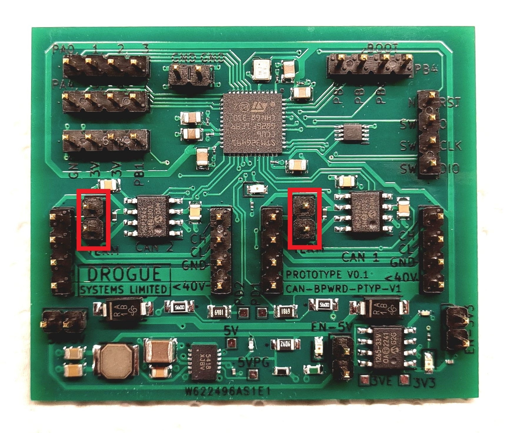
With the jumper in place, the termination resistor is connected to the CAN bus, and provides 120 Ohms of resistance between the CAN High and CAN Low pins on the network.
Tip: On a properly configured CAN bus, the measured resistance between CAN High and CAN Low should be around 60 Ohms, this is due to there being a 120 Ohm termination resistor at each end of the network, forming a parallel resistance of (1 / (2/120)).